🛒 Best Price Today on Amazon
Prime members get fast, free shipping on everything above, plus member-only deals. New members get a 30-day free trial — cancel anytime.
- What does actuation distance actually measure?
- What tools do you need for a useful physical test?
- How do you measure a fixed actuation point?
- How do you measure reset and Rapid Trigger separately?
- How can you tell whether a small change is meaningful?
- What should you check if the readings seem wrong?
- Conclusion
Set a fixed actuation point, turn off Rapid Trigger, and zero a gauge at the resting keycap. Then move the key in small steps and record the first key-down event. That is how to measure actuation distance on a magnetic gaming keyboard without treating its software slider as a physical measurement. Repeat before drawing a conclusion.
What does actuation distance actually measure?
Define zero from the same point on the resting key
Actuation distance is the downward travel from the fully released position to the first registered digital press under a specified configuration. If a key rests at the zero point you selected and the operating system first sees it at a reading of 1.2 mm downward, you observed a press around that depth. The measurement is clearer when you also know the last point where the key did not register.
Total travel is the distance to the bottom stop. Reset depth is where the keyboard releases an already active key as it moves back up in a fixed configuration.
The difference between those values can help explain how a key feels, but each describes a different part of the stroke. A measurement of bottom-out travel alone says little about where the key first registers.
Start by measuring one familiar key rather than the whole board. Choose a normal one-unit key such as an unused letter or movement key and avoid Space, Shift, or Enter for the first tests. Larger stabilized caps can tilt or bind differently depending on where you press them.
Treat the value in the keyboard app as a setting
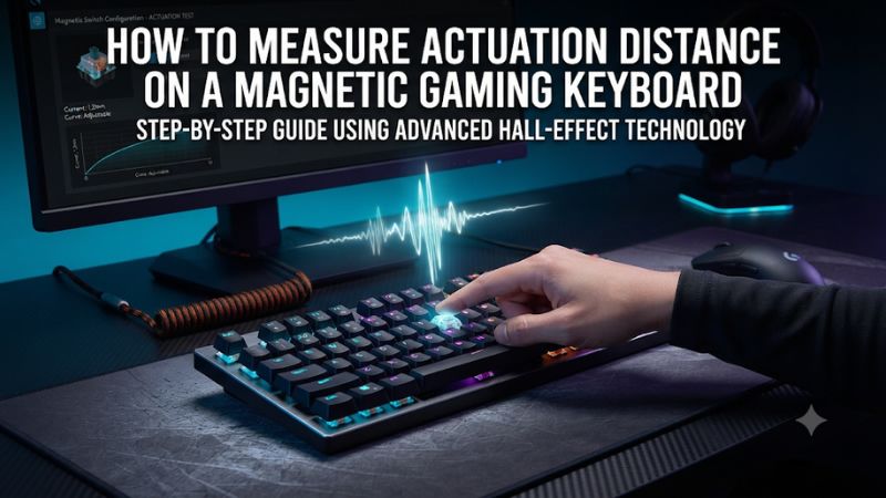
A magnetic keyboard converts the position of a moving magnet into a signal, then maps that signal to an estimated travel and output. A software slider sets the desired behavior. It can be useful for tuning even when its label and measured physical depth do not line up exactly.
RTINGS measured physical position against USB responses in its adjustable-input research and found some overlap between neighboring settings. That is a reason to run repeated tests before calling a small discrepancy a fault. A slider step of 0.1 mm describes how closely you can space settings in the interface, independently of how closely the hardware follows each one.
An on-screen live travel graph can help confirm that the correct key or profile is active. Its scale can be based on the same sensor and calibration as the firmware. Use an independent gauge if your goal is to find physical distance and use an independent key-down indicator to confirm when the host sees an input.
| Measurement | Starting point | What to record |
|---|---|---|
| Fixed press actuation | Fully released key | Last depth with no press and first depth with a press |
| Fixed reset depth | Already actuated key moving up | Last held depth and first released depth |
| Total physical travel | Fully released key | Position at the first firm bottom stop under normal pressure |
| Rapid Trigger release movement | A known held depth | Upward distance before a key-up event |
| Rapid Trigger reactivation movement | A documented reversal point after release | Downward distance before the next key-down event |
Disable features that change the event during a stroke
Use a digital keyboard output for the first test. Turn off Rapid Trigger, multi-action bindings, analog gamepad output for the test key, and direction rules such as SOCD processing when the board offers them.
Confirm the key sends an ordinary key-down and key-up. Use the same saved profile throughout a measurement series.
Rapid Trigger can release or reactivate after movement relative to a changing position. That is useful in a game and can make a repeated press happen at a different absolute depth from the first one. Bench testing a fixed activation setting and characterizing that movement mode should be separate tasks.
Start around the middle of the adjustable range, such as a 1.0 or 1.5 mm setting where available. That makes it easier to learn the procedure without being close to a deadzone or bottom stop. Complete any routine calibration the manufacturer calls for, then note the profile, setting, key, mode, firmware, and connection.
What tools do you need for a useful physical test?
Choose a way to read vertical key movement
A dial indicator or digital indicator on a rigid stand is a good starting point if you can position the probe nearly along the switch’s movement. A digital depth gauge on a stable reference bridge can also work.
With a caliper, avoid letting the tool rock or using it to pinch the cap. Use it in a stable arrangement that can reference the same point consistently.
Check the tool’s resolution and repeatability before choosing your step size. A display that shows hundredths can still produce larger variation if it is mounted poorly.
Test it by returning to zero several times with the keyboard stationary. Report results no finer than the repeatability of the setup supports.
Use only light contact at rest. A spring-loaded probe can move a light switch before you zero it.
If that happens, lower the contact force or change the fixture so you can set the rest reference without moving the key. Verify that key-down remains clear at zero and that the height reading returns there after a press.
Use an input display that shows the event you care about
Use a trusted local key-event display or a simple keyboard tester that visibly distinguishes key-down from key-up. Check that the selected key registers once when you press and remains indicated while you hold it. If you use a browser-based tester, keep focus in its window and pick a key that will not open menus or shortcuts.
A plain text editor is a useful backup for detecting the first character. It is less convenient for release measurements and can repeat the character if you keep holding the key. For precise observation, ignore operating system auto-repeat and follow only the first change from up to down or from down to up.
Connect directly by USB for a stable starting condition when the board has that option. A wireless link is usable for a settled hold test if it is reliable, but record which mode you used.
The procedure below estimates travel. It does not measure end-to-end response time.
Stabilize the board, the gauge, and the press
Put the keyboard flat or at its usual fixed angle on a solid surface, away from an unstable mat or hinge. Keep the case from sliding without pushing on it in a way that changes its shape.
Align your gauge with the direction the key actually moves. When the board is tilted, gravity and the switch axis do not necessarily point along the same line.
Measure at one clearly identified spot, near the center of a cap. Apply force straight along the switch axis using either a controlled fixture or a nonmagnetic pusher if it helps.
Keep spare magnets, magnetic trays, and magnetic tools away from the key area. A setup that lets you settle the cap without changing your grip gives more useful readings than trying to catch a number while pressing quickly by hand.
If the probe and the tool applying force contact different parts of the cap, ensure they do not tilt it relative to the switch. You can use a rigid guide or a small flat pusher with room for the probe. Never jam a tool between caps or force the key through its normal travel.
How do you measure a fixed actuation point?
Establish a repeatable zero
- Release the key completely. Confirm that the event display shows the key up and the spring has returned it to its resting position.
- Bring the gauge into light contact. Position it so the setup remains square to the stroke and the cap does not visibly move under the probe.
- Record or zero the reading. If the gauge counts in the opposite direction, record which way the depth increases and use the magnitude of the difference.
- Check zero again. Press and release gently, then verify that the position returns near the same value. If it does not, fix movement in the stand or cap before taking measurements.
Use a midpoint setting for a practice pass and move the key from rest to near the point where it registers. This confirms that you can move the gauge setup smoothly and that your event display has focus. Keep the first pass separate from the measured runs, particularly if the board automatically settles or recalibrates after startup.
Approach the threshold in short steps and pause
- Move downward without reversing. Advance until you are near the anticipated point. Use small steps matched to your fixture, such as 0.1 mm for a basic bench setup.
- Hold each position briefly. Give the host display enough time to show an event while the gauge is stable. Record the deepest step that still shows the key up.
- Record the first step that shows key-down. The physical threshold is bracketed by that value and the preceding inactive step under your test conditions.
- Release completely before repeating. Return to the same rest reference and run another downward approach. Approaching from the other direction can measure reset or a different feature.
If 1.10 mm is inactive and 1.20 mm is active, report that bracket and avoid assigning an exact threshold to its midpoint. A separate series with smaller steps around that interval can narrow the estimate if the fixture stays repeatable. For example, a 1.15 mm step is useful only when the setup can hold and read that increment consistently.
A quick press followed by reading the gauge can overshoot the trigger depth. The settled step approach limits that error. It also avoids confusing how fast a web page refreshes with how far the switch moved.
Repeat, summarize, and compare two useful settings
Take five or more measured passes on the same key. Keep the last inactive and first active depths for each pass.
A median of the first-active values can summarize the runs, provided you also report the interval width and the spread. Results with the same number on the screen can still have uncertainty from the step size.
For example, imagine first-active readings of 1.20, 1.20, 1.15, 1.20, and 1.25 mm using a repeatable 0.05 mm step. The median first-active reading is 1.20 mm.
The individual threshold brackets still matter. A report that says 1.20 mm was the typical first-active step conveys more than treating that figure as the exact physical threshold.
Then change only the configured actuation to a meaningfully different value, such as from 1.0 to 2.0 mm if supported. Repeat the same procedure.
If the physical threshold clearly moves deeper, your keyboard is responding to the setting even if the measured distance differs from the displayed value. Verify a smaller change only if your setup is repeatable enough to distinguish it.
How do you measure reset and Rapid Trigger separately?
Measure a fixed reset while releasing the key
After recording press actuation, hold the key far enough down that it is clearly active. Move upward in small steps, holding each position as before.
Record the last position still showing key-down and the first showing key-up. Use the same zero reference so you can compare press and release depths on the same scale.
If the press threshold brackets overlap the reset brackets, your setup may be too coarse to resolve the difference. A repeated up-versus-down result is more informative than one press and one release that happen to show different numbers. Note the direction of approach for each record.
Do not assume the difference between those two depths equals a Rapid Trigger sensitivity setting. Fixed reset behaves relative to the stroke and its configuration. A dynamic release test depends on where the key starts moving in the other direction.
Test dynamic movement from an identified depth
Enable Rapid Trigger for only the key you are testing if the software allows it. Record the actuation threshold and the release and press sensitivities.
From rest, cross normal actuation and stop at a known held depth below that point. Then move up in settled steps and note the depth at key-up.
To express the upward movement, subtract the key-up depth from the held depth. If you started at 2.00 mm and first observed key-up at 1.75 mm, the first released step is 0.25 mm above the starting depth.
Keep the last-held step as the other bound. Avoid major changes near bottom-out or top-out unless you are specifically investigating deadzones.
For reactivation, document the exact point where you reverse downward after release and observe the next key-down. Compare the movement from that point, not the distance from the top.
Model options can change when Rapid Trigger becomes active or remains active. Follow the device’s behavior and keep the saved profile with the result.
How can you tell whether a small change is meaningful?
Compare shallow, middle, and deeper settings with the same setup
After verifying one middle setting, choose a shallower and a deeper option supported by your board. Keep the same switch, cap, key, mounting position, and gauge.
Test five presses per setting in the same manner. Check the rest zero before each new group so a shifted fixture does not look like a changing actuation point.
Compare the ranges from the three groups. Clear separation between the brackets shows that the selected settings behave differently on that key under your test conditions.
If adjacent settings overlap, record the overlap and look for a wider separation that your setup can distinguish. A split between two settings on two different keys may also reflect per-key calibration or mechanical variation.
Take care near the shallow limit. If the probe moves the key enough to trigger it, reread the rest reference and use a fixture with less contact force.
The bottom of travel deserves similar care. Stop at normal bottom-out and avoid compressing the case or plate to chase a number beyond the key’s stroke.
Distinguish deadzones from the fixed threshold you configured
A top deadzone is a part of the stroke near rest where small movement is ignored or cannot be usefully resolved. A lower limit can affect the behavior near the bottom of the stroke.
The first digital press under one fixed profile includes the effect of that chosen profile. It is not necessarily a direct measurement of the entire sensing range.
If your only goal is to verify a 1.5 mm gaming setting, record the digital press and leave analog resolution out of the conclusion. If you also want to investigate fine travel behavior, observe a supported live travel display alongside the gauge. Report whether the display moved and keep its software estimate separate from your measured depth.
A basic step test is good for finding large discrepancies and comparing useful settings. It does not measure how fast the host receives an event during a fast press. If response time is what you want, compare latency measurements made with a synchronized event and movement setup.
What should you check if the readings seem wrong?
Verify the profile, the test event, and the fixture in order
- No key-down at any depth. Check that the key maps to a digital input and that the event display has focus. Confirm the key works in ordinary typing and the intended profile was applied.
- A press appears at zero. Remove pressure from the probe, restore a less sensitive test setting, and verify that the key returns fully. Check model-specific calibration if the problem persists.
- The event arrives at different depths on every pass. Inspect movement of the stand, the probe angle, and how lightly you contact the cap. Test a wider bracket and a different normal-sized key.
- A second key gives a different result. Verify per-key settings, switch compatibility, and calibration. Compare another key before assuming the entire board is defective.
- Closely spaced settings overlap. Choose two widely separated settings and repeat. Report what the setup can distinguish rather than forcing a conclusion from very small increments.
Use a stable USB connection and test with a standard profile before investigating firmware. A drifting zero or poor fixture can produce an effect that looks like a sensor problem. A repeatable mismatch across different settings is more useful for reporting an issue than one noisy trial at the shallowest setting.
Record enough detail for someone else to repeat the result
Write down the keyboard and switch version, firmware, physical key, gauge and step size, connection, and profile settings. Include how you checked zero and whether the keyboard was flat. Record the raw brackets for both the fixed and dynamic tests if you ran them.
Report uncertainty plainly. A result that repeats within 0.1 or 0.2 mm is useful for choosing between substantially different settings, even if it cannot confirm every small software increment. Keep any illustrative numbers separate from your own observations.
On a capped key, the reading describes travel at the cap location you measured. Leave the same cap on for all comparisons or record any change. Switching between a bare stem and a sculpted cap can change how the probe sits and make small differences hard to interpret.
Conclusion
Use a fixed profile, a stable gauge zeroed at rest, and a digital key-down display. Press in settled steps and record the bracket between the last inactive depth and the first active depth. Repeat before judging a software value, then use a separate procedure for release and Rapid Trigger if those are the behaviors you need to compare.