🛒 Best Price Today on Amazon
Prime members get fast, free shipping on everything above, plus member-only deals. New members get a 30-day free trial — cancel anytime.
- What should you check before removing the first switch?
- How do you remove a cap and switch without damaging nearby parts?
- How do you align, seat, and test a replacement?
- How do you diagnose a dead key, chatter, or an RGB change?
- How can you prevent the most common fit mistakes?
- How should you finish a full keyboard swap?
- Conclusion
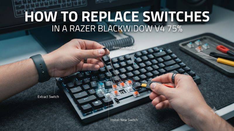
Unplug the wired BlackWidow V4 75% and try a single compatible mechanical switch on a small key. That is how to replace switches in a Razer BlackWidow V4 75% without risking a whole set at once. Use the included puller to release both clips, align the replacement pins, and confirm the press and release before moving on.
What should you check before removing the first switch?
Confirm the model and the scope of the job
Check that you have the wired BlackWidow V4 75%, model family RZ03-0500. The keyboard’s supported swap takes place through the top plate.
Other BlackWidow V4 variants can have different designs, and the V4 Pro 75% has its own manual. Look up your exact variant before assuming the same procedure or included tool.
The wired V4 75% comes with preinstalled Orange Gen-3 tactile switches in its standard configuration. Keep at least a few of them. One original switch that you already know works is useful when you need to check a new part or recover the regular feel of a frequently used key.
A switch swap does not require disassembling the case, touching the PCB, or exchanging stabilizers. Razer’s product guidance says internal damage caused by internal modifications is outside its warranty coverage. When the job turns into investigating a loose socket or other internal problem, stop the top-side swap and use the applicable support path.
Pick a standard mechanical replacement
Razer says most standard three-pin or five-pin mechanical switches fit this model. Its product FAQ points to compatible Razer Green Clicky and Yellow Linear choices for people who want a different feel from the stock Orange tactile.
Third-party parts can be useful too. Try a sample if a housing, cap clearance, or RGB result is uncertain.
The two metal contacts and plastic center post guide a conventional three-pin switch into place. A five-pin mechanical design adds two plastic locating legs.
Fit requires the right mechanical housing and electrical contact layout. A similar stem shape or housing outline does not make an optical, magnetic, or low-profile switch a substitute.
Use a sample before buying a full set from an unfamiliar family. Seat it on a single-width key, install the cap, and test both input and feel. Switches with different tops can spread per-key light differently even if both register correctly.
| What you are changing | Test first | What a good result looks like |
|---|---|---|
| One failed key | Same key with a known-good compatible switch | One clean input on each distinct tap |
| A quieter or lighter group of keys | One ordinary key with the planned switch and cap | Smooth return and a feel you prefer |
| The complete set | One small batch, including ordinary letters | Every change works before you move to the next row |
| A large key such as Space | Cap alignment and both stabilizer sides | The cap returns evenly and neither end binds |
| RGB appearance | One replacement with your regular effect | Expected input and acceptable light spread |
Preserve your layout and prepare the tools
Use Razer’s included two-in-one switch and keycap puller or suitable separate pullers. Put the keyboard on a stable work surface and use bright lighting to see thin contacts and clips. Get a container for switches and keycaps so you can keep tested and untested parts apart.
Take a photo of the top, especially the right navigation column and the bottom row. Some cap shapes and widths look similar when loose.
Refer to the original positions as you reinstall them. Save or note any Synapse assignment that might change what a test key sends.
Choose a normal key that you can test in a plain text editor, such as a letter. Hold off on a large stabilized cap until the first installation works. A standard cap and a known character make it easier to recognize when the problem is the swap itself.
How do you remove a cap and switch without damaging nearby parts?
Disconnect the wired board and remove the target cap
- Unplug the USB cable. Confirm the board’s lights are off before you work. Move the cable away from the edge so it cannot pull on the board.
- Use the cap-puller end. Set it around the cap so both sides hold evenly. Keep it clear of neighboring caps and pull straight up.
- Check the cap stem area. If one side catches, set it down and reposition the puller. Avoid twisting the cap while the puller grips only one edge.
- Keep the cap identified. For one key, set it near the keyboard. For a full set, preserve row order and the orientation from your photo.
If you try a large cap, use even upward force and stop if a middle or side support hangs up. Large keys use stabilizers. Their resistance can feel different from a one-unit cap, so do not assume the switch needs additional force simply because one side of Space sticks.
If nearby caps block your view of the housing, remove only the one or two you need to reach both tabs comfortably. This is easier to reassemble than clearing an entire row and still lets you see the correct position for the switch puller.
Use the switch end to release both clips together
Position the hooked ends of the switch puller at the retention clips that hold the housing in the plate. Grip the clips rather than the center stem, then squeeze enough to release them. Lift straight upward while you keep the switch level.
If one edge of the housing lifts and the other stays put, stop. Lower the raised side and move the tool so the second hook reaches its clip.
The case or plate should not be your lever. Rocking hard can bend a contact as it leaves the socket or damage a surrounding part.
Keep the tool away from the LED and socket openings. If the switch still resists after you can see both tabs engaged, check the model guide’s diagram and try a better-fitting puller. A switch with broken clips or visible damage deserves a separate inspection before you pull harder.
Inspect the original and empty position
Look at the underside of the original. See where the two metal contacts and center post align with the empty position.
Use that switch as an orientation reference. A square outline can make a rotated switch look as though it should fit.
Examine the visible opening from above. If a contact appears torn off and stuck inside or the socket area looks shifted, avoid probing it with the puller.
A top-side swap should leave the board and its contacts in place. Document what you see for support before trying another part.
Set down the original in a way that protects its pins. If it came from a misbehaving key and you have other stock switches, mark it separately. This prevents a suspected faulty switch from being reused as your comparison part.
How do you align, seat, and test a replacement?
Compare the pins before bringing the new switch to the plate
Check both metal contacts, then compare the plastic locating points and the clips with the original. Use a straight, undamaged replacement for your first test.
If a contact is folded, loose, or creased, set the part aside and use a good sample. A contact that is already bent can create a dead key even when the housing looks seated.
Check the position at the socket above the board. Hold the switch square to the plate and let the guides start into their openings lightly.
If you cannot place it straight without pressure, lift it back out and check orientation. A compatible switch should never need force to overcome a misaligned pin.
The color or logo on the top can be a useful visual reminder after you verify actual pin orientation. Some switch brands face a different direction on their packaging photos. Trust the underside and the positions in your board.
Seat the switch fully and reinstall the right cap
- Lower the switch squarely. Keep both pins and the center post aligned with the openings.
- Press evenly near the center. Use only the pressure needed for the clips to seat. Stop if the switch hangs high or tilts.
- Check for a flush fit. Compare its housing with a neighboring switch. If it sits higher, remove it and inspect the contacts before trying again.
- Replace the cap. Put it in its original orientation and test its return by hand before reconnecting USB.
A compatible switch may feel firmer or lighter than the original and still work properly. Focus first on smooth motion, fully returned height, and no physical interference. Compare pressure or sound only after the key is operating correctly.
If a long key works in the center and catches at one end, inspect whether its cap sits evenly on both stabilizer mounts. A change in switch weight can reveal an existing seating issue. If the switch alone moves freely, changing to another switch is unlikely to correct a cap that catches at its edge.
Use a plain input test before opening Synapse
Reconnect the keyboard directly to the PC with a data cable. Open a text editor or trusted tester and press an untouched key first.
That establishes a working USB route. Check the newly installed key in the same window and make sure the event belongs to the position you changed.
- Tap deliberately. Press the key several times, allowing a full return between taps. Each press should produce the expected event once.
- Hold and release. Confirm key-up in a tester where available. A held letter repeating in an editor can be normal.
- Test a modifier. Check the key with Shift or a combination you use regularly. Verify changed game bindings only after basic Windows input works.
- Reload the regular profile. Test your Synapse assignment and Chroma effect separately after the plain test passes.
If a configured action differs from the physical legend, compare the active map with the normal profile before labeling the switch as defective. A correctly operating switch can send another key or run a macro because of an assignment.
How do you diagnose a dead key, chatter, or an RGB change?
Follow a dead key through a controlled substitution
Unplug the board, remove the new switch, and inspect both contacts. Replace it temporarily with a known-good compatible switch. If the original was already faulty, choose a working part from a different position rather than assuming the original is a reliable control.
If the known-good switch works in that position, the board can receive input there. The new switch may have a damaged pin, fit problem, or internal fault.
If the new switch is visibly undamaged, you can test it in a known working position. Power down each time you make a physical change.
If two known-good parts both fail in the same socket after you return to a normal keymap, stop swapping. Document the physical position and the test result.
The next step may be board support instead of another switch. If multiple keys fail or none are detected, investigate the direct cable and USB connection before claiming several sockets failed together.
Separate chatter from repeat settings and macros
A single fully released tap that produces two or more events points to a different issue from repeated characters during a long hold. Use deliberate individual presses with no active macro or reassignment.
Observe ordinary repeats separately. Compare several slow taps and several fast taps on the same key.
If doubling follows one switch to another position, set that switch aside and use a known-good part. If it stays with one location, check the normal keymap and confirm a direct USB connection.
Repeat the result once before contacting support. Keep a short record of the setting and which switch you tried.
If the key behaves normally in a text editor but sends multiple actions in a game, check the game’s own input assignment. Test the same sequence with Synapse customizations disabled where possible. That gives you usable evidence about the path where the issue begins.
Check RGB and sound after the key works
A new switch housing can change the light’s color, spread, or apparent brightness. Use a simple static effect and compare the changed key with its neighbors. If the darker spot follows a specific housing while keys register normally, the results can reflect how the switch transmits light.
If several LEDs or a full section stop responding together, check the Chroma effect and test the normal profile. Removing more switches is unlikely to explain a global lighting behavior. Keep your work on the one physical position until the click, cap clearance, and input are all understood.
Try typing a short passage after replacing a group. A softer, louder, or different sounding key can be the change you intended.
A scraping or sticking sound with the cap installed warrants a clearance check. Compare the same switch with and without that cap before changing another part.
How can you prevent the most common fit mistakes?
Check the clearance of a second row before committing to a set
Test the switch with both the original cap and the cap set you intend to keep. Do that on a normal key in the middle of a row, where neighboring caps can reveal a clearance issue.
Then check the same switch on a second row, since caps can have different shapes and heights. Press near the center and on both sides and watch whether the cap comes up freely.
If it moves well with the cap removed and catches with the cap installed, first reseat the cap. Then put back the original cap or move a known-good compatible cap onto that key to isolate the source. If the cap touches the housing or its neighbor, pick a fit that clears rather than assuming a deeper push will help.
Test how the switch top spreads the light on a plain Chroma color if that matters to you. A transparent, frosted, or opaque housing may change the appearance at the legend and around the cap. The focus of the check is whether you like the result in the row you plan to replace.
Compare the new movement cluster without changing its assignments
For a mixed switch setup, try one common arrangement first. Keep the remaining bindings and switch positions normal while you change a single high-use key.
Use a game sequence with repeated holds and releases. Check whether your preferred tactile or linear feel is actually easier to control during that sequence.
If you are switching from the stock Orange tactile to a linear switch, give yourself time to get used to the absence of a bump. For clicky switches, record a short sample while your voice app is open if the sound of repeated presses matters to your calls. The decision can rest on how the switch works in your own room rather than on a stock sound recording.
Keep the original switches from each modified area in a separate container if they differ by condition or feel. A known-good spare also helps when a key stops responding later. Leaving one original installed beside a few new ones gives you a reliable reference without needing a second board.
Know when to stop after a failed installation
If the switch will not seat normally, inspect it again away from the board. Compare its contacts with the original and check the locating legs as well as the stem.
A bent leg or a folded metal contact identifies a fit problem before you apply more force. Use a fresh compatible sample when there is visible damage.
If a known-good part fits several other keys but sits unusually high at the failed position, stop and inspect from above. Note whether the plate opening or visible socket area appears different.
Avoid using a tool to spread the plate or hold the socket. The manufacturer or a qualified repair route is more appropriate if the problem goes beyond a normal hot-swap.
If the failed key was already unreliable before you touched it, keep the evidence that proves that difference. Write down the part tested, whether the failure followed it, and whether the rest of the board works. This helps distinguish a switch fault from a persistent board or input configuration issue.
How should you finish a full keyboard swap?
Work in groups and keep a record of changed positions
Swap a handful of normal keys and reconnect to test them before starting the next group. Use a printed or photographed layout if you are mixing weights or switch types. This makes it easier to confirm that a familiar movement group still feels the way you intended, especially when the change covers more than one row.
After the ordinary keys, work through larger caps one at a time. Confirm the key sends correctly, then check physical return when you press either side.
Keep all original parts until you have run a full game and a normal typing session. They let you restore an important key quickly if you dislike the change.
Finish by testing the function row, arrows, common modifiers, and any keys you changed for gaming. Restore your daily profile and lighting only after the plain input pass. If everything works by direct USB with a standard keymap, you have a useful baseline for future troubleshooting.
Conclusion
Unplug the wired BlackWidow V4 75%, use the cap puller and switch hooks on one ordinary key, and seat a compatible replacement with straight pins. Test distinct taps and release before changing the rest. If a problem stays with the socket after a known-good substitution and a standard keymap, document the failure and contact support.